Phone:
+86 13828 600940
Physical address:
No.8Liyuan Road, Bogang community, Shajing Street Baoan District, Shenzhen, China
Phone:
+86 13828 600940
Physical address:
No.8Liyuan Road, Bogang community, Shajing Street Baoan District, Shenzhen, China
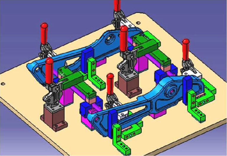
The main purpose of using a fixture is to ensure the size (shape) accuracy and position accuracy of the processed parts.
Factors affecting workpiece manufacturing accuracy: In addition to machine tool and tool factors, machine tool fixtures must meet design accuracy requirements.
Traditional fixture manufacturing processes: Most still use the assembly and adjustment method. This fixture manufacturing process is similar to conventional mechanical
manufacturing.
All parts are manufactured according to the part drawings and then assembled. The final fixture accuracy depends on trial and error adjustments or grinding of the position or size of a certain part.
Disadvantages of traditional fixture manufacturing: From a practical application perspective, it is difficult to meet the various dimensional and shape tolerance requirements in the assembly drawing.
Therefore, in order to ensure the manufacturing accuracy of the fixture, special process methods must be adopted. The following five process methods can ensure the accuracy of the fixture.
Method definition:
This refers to the simultaneous machining of identical structural elements on multiple fixture components. These structural elements typically include geometric dimensions or cross-sectional shapes, as well as their relative positions. Identical machining conditions ensure the quality and interchangeability of fixture components, thereby improving overall fixture manufacturing accuracy.
Method classification:
According to different manufacturing methods, group processing can be divided into two specific process methods: “paired processing” and “mirror processing”.
Pairing processing:
It means that all paired components in the fixture are processed in pairs through “combined grinding”, “combined boring”, “combined drilling”, “combined reaming” and other methods to eliminate dimensional errors and position deviations between workpieces.
Practical applications: preparation of dowel pins, boring of guide holes, grinding of profile blocks, etc.
Mirror processing method:
It refers to the process of processing certain fixture components with symmetrical structures, firstly processing them to double the length and adding equal allowance workpieces with the symmetrical plane as the boundary, then cutting along the symmetrical plane, and then combining the two symmetrical parts using the mirror principle after processing to eliminate the symmetrical error.
Case:
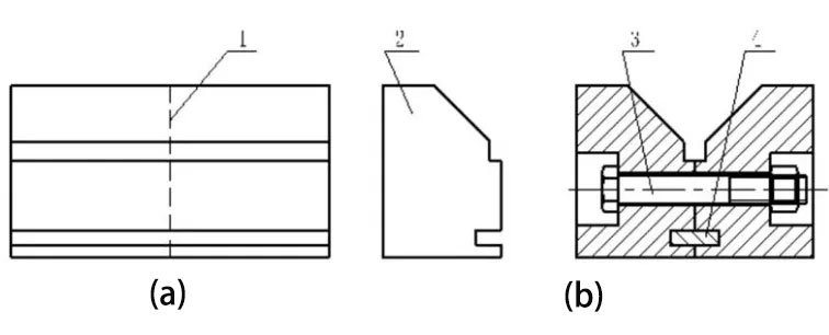
V-shaped positioning blocks are designed with automatic centering capabilities, requiring extremely precise symmetry between their two working bevels. Traditional V-block manufacturing methods typically involve integral fabrication, with final finishing of the two bevels often performed on a surface grinder using a precision sinusoidal fixture and V-shaped magnets. However, this method struggles to ensure ideal V-shaped symmetry.
Practical Application:
When using the mirror processing method, the V-shaped block is first made into a single semi-finished product as shown in Figure (a), cut and processed along the symmetry plane, and then assembled into a combined V-shaped block using positioning keys and connecting bolts as shown in Figure (b).
Process characteristics: No high-precision machine tools are required, and the symmetry of the V-shaped block can reach extremely high precision with the help of ordinary machine tools.
Main application: used to manufacture symmetrical structures or multiple repeated fixture components.
Method definition:
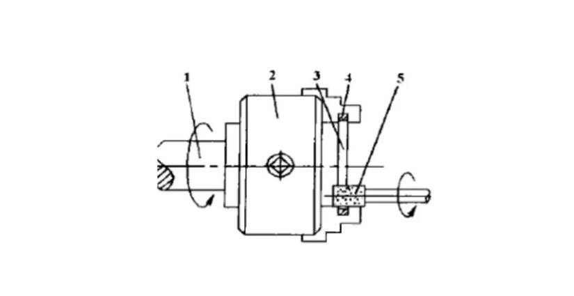
The cutting function of the machine tool where the fixture is located is used to cut another part, eliminating the positional errors between them and ensuring that each part occupies the ideal position, thereby improving manufacturing accuracy.
Process features: Final processing is performed on the machine tool where the fixture is located to ensure fixture accuracy.
Main Application: Used in the machining process of fixture positioning components to ensure the final accuracy of the movement in machine tool assembly.
Typical applications: Grinding machine fixtures for grinding external cylindrical shafts and internal surface grinding, lathe spindle fixtures, milling machine worktables, and surface grinder electromagnetic chucks.
Process advantages: Eliminate errors in fixture manufacturing, assembly and installation, and ultimately achieve extremely high precision.
Conditions of use: Temporary machining method is only applicable to machine tools with temporary machining conditions.
Drawing design: When the designer requests to use this process method to design a fixture, it is necessary to indicate on the fixture general drawing that “reserve finishing allowance according to the drawing size, pending final processing by the machine tool.”
The alignment-then-fixing method usually uses universal measuring tools.
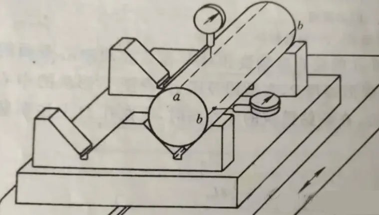
Application example: Alignment and fixation of V-shaped locating blocks. The installation and processing of the locating key, locating groove and bolts on the V-shaped fixing blocks have been completed.
Method and Procedure: Use a dial indicator to align the upper and lower busbars of the mandrel with the measuring busbars, ensuring that the mandrel is parallel to the surface of the locating key (the side of the T-slot) and the fixture mounting datum. This alignment process requires repeated adjustment and grinding. Once completed, tighten the screws, drill and ream the retaining pin holes, and drive the retaining pins in.
Process characteristics: The accuracy of alignment depends on the worker’s technical level, the accuracy of the measuring tool and the accuracy of the measuring benchmark.
In fixture design, we often encounter inclined holes and inclined surfaces with high requirements. Due to the limitations of processing equipment, the inclined holes and inclined surfaces need to be placed in a vertical or horizontal position for easy processing.
Due to measurement technology difficulties, its dimensions cannot be directly measured and controlled during processing. Therefore, it is necessary to set a process reference hole as a transition reference to convert the dimensions to be controlled into process dimensions that can be directly measured or controlled.
By controlling the converted process dimensions, the design dimension requirements of the workpiece can be indirectly guaranteed. This process method is called the transition reference method and has been widely used in fixture manufacturing practice.
Application Cases:
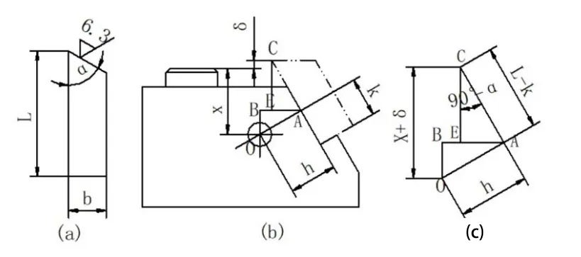
As shown in the figure above, under the premise of ensuring the dimensions h and K, as long as the distance from the working surface of the tool block to the axis X of the process reference hole O is guaranteed, the processing requirement of the long side dimension L can be guaranteed.
In addition, when processing certain large boring dies on a boring machine, using the process reference hole as the transition reference is a commonly used and effective process method.
When using this method, after the boring die is assembled as a whole, the pilot holes with higher coaxiality requirements can be machined sequentially from both ends of the boring die. After the horizontal boring head completes the pilot hole at one end of the template, the vertical boring head is used to machine two process reference holes at both ends of the template. The centers of the holes should intersect perpendicularly with the centerline of the machined pilot holes.
The boring die is flipped over, and a cylindrical pin is inserted into the process reference hole. A dial indicator is clamped to the vertical boring head, and the crossbar is moved back and forth to calibrate the center position of the cylindrical pins at both ends. Once aligned and fixed, the guide hole of the other end of the template can be machined. Because the fixture is assembled as a whole and then machined, this method ensures high coaxiality.
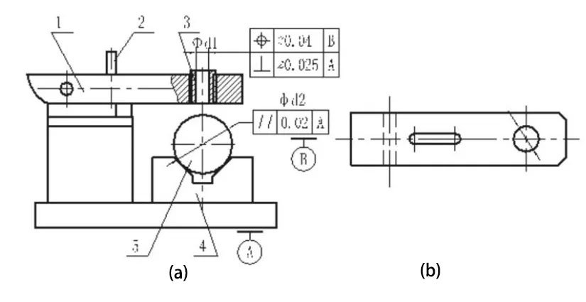
Design requirements:
The verticality of the center axis of the drill sleeve inner hole φd1 to the installation reference surface A, as well as the position accuracy of the center plane of the V-shaped locating block.
Processing technology:
On the jig boring machine, align the center plane of the V-shaped locating block, tighten the butterfly nut after assembly, and bore the bottom hole of the bushing on the drilling template.
Process Features: Relying on the precision of the jig boring machine to directly guarantee the required fixture positioning accuracy is the most effective method for ensuring perpendicularity between the drill sleeve center axis and the fixture installation reference surface. This process is commonly used to machine the guide sleeve bottom hole of drilling and boring fixtures.
Design requirements:
The positions of the two V-blocks are determined by the height dimension H and the horizontal dimension L, and the sides of the two locating keys are represented by the datum B. The fixture design requires that the locating surfaces of the two V-blocks must be in full contact with the workpiece while ensuring the two parallelism requirements.
Process:
To ensure the parallelism of H, L and both, the two V-blocks can be processed into inclined surfaces when manufacturing the fixture, and semi-finished products with sufficient grinding allowances can be reserved. The V-blocks can be assembled onto the fixture body, and the V-blocks and the fixture body can be fixed with tapered pins.
On a tool grinder or guideway grinder, using A and B as positioning references, grind the 90° bevel of the V-block to meet the H, L and two parallelism tolerance requirements.
When applying the assembly processing method to fixture design and manufacturing, it is necessary to be familiar with the manufacturing process characteristics of the assembly processing method and meet the requirements in terms of structural design, size and shape tolerance marking, fixture component processing and technical conditions formulation.
Compared with traditional fixture design, fixtures manufactured using assembly processing methods have significant differences in drawing design and should include four types of design drawings: fixture assembly drawing, fixture guide structure (such as drill sleeve, boring sleeve, etc.) assembly processing drawing, fixture guide component pre-assembly drawing (i.e. semi-finished product drawing), clamping mechanism and clamping details and other product drawings.
The purpose of using these four drawings at the same time is to prevent the fixture manufacturing department from still using the process route of “making parts → assembling components → adjusting accuracy” during the fixture manufacturing process, thereby guiding and constraining the entire fixture manufacturing process.