Phone:
+86 13828 600940
Physical address:
No.8Liyuan Road, Bogang community, Shajing Street Baoan District, Shenzhen, China


Automotive welding fixtures are specialized tools used to secure and position vehicle body parts during the automotive manufacturing process. Their primary purpose is to ensure the welded parts maintain their precise position during the welding process, guaranteeing the consistency and reliability of welding quality. They are an important means of connecting automotive parts, not only determining welding accuracy and stability but also directly impacting production efficiency and product quality.
In the manufacturing industry, fixtures are widely used tools with many types, which can be roughly divided into the following categories:
Universal fixture
Machine tool vise : used for milling machines/drilling machines, clamping regular workpieces, divided into mechanical and hydraulic types.
Three-jaw chuck : lathe core fixture, automatic centering of circular workpieces, accuracy within 0.05mm
Magnetic chuck : specially used for grinding machines, it fixes magnetic metal parts through electromagnetic fields.
Special fixture
Welding combination fixture : modular positioning system, suitable for welding special-shaped structures (such as automobile chassis)
Inspection fixture (CMM fixture) : used with three-dimensional coordinate measuring machine, including precision V-block and adjustment mechanism.

| Fixture type | Core Features | Typical application scenarios | Technical Features |
|---|---|---|---|
| Positioning fixture | Limiting the workpiece’s degrees of freedom | Milling machining center | 3-2-1 positioning rule, error ±0.01mm |
| Clamping fixture | Resist cutting forces | Heavy parts boring | Hydraulic boost ratio ≥1:50 |
| Indexing fixture | Precise indexing in the circumferential direction | Gear machining/polyhedron milling | Worm gear transmission, resolution 0.1° |
| Combination fixture | Modular rapid reconstruction | Small batch and multi-variety production | Hole positioning accuracy ±0.005mm |
CNC machine tool fixtures
Zero point positioning system: equipped with HSK/T-slot, changeover time < 30 seconds
Vacuum adsorption platform: large-area thin plate processing (such as PCB drilling and milling), vacuum degree ≥ 0.08MPa
Automated production line fixtures
Robot gripper: integrated force sensor, adaptive adjustment of gripping force
Pallet exchange system: with FMS, positioning repeatability accuracy ±2μm
Automotive tooling: Multi-axis synchronous clamping mechanism for engine cylinders
Aviation fixture: Anti-deformation frame for titanium alloy wing spar parts
Electronic fixture: Precision alignment platform for SMT placement machines
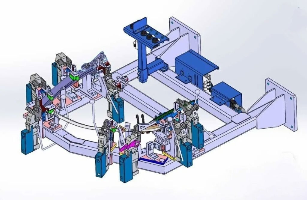
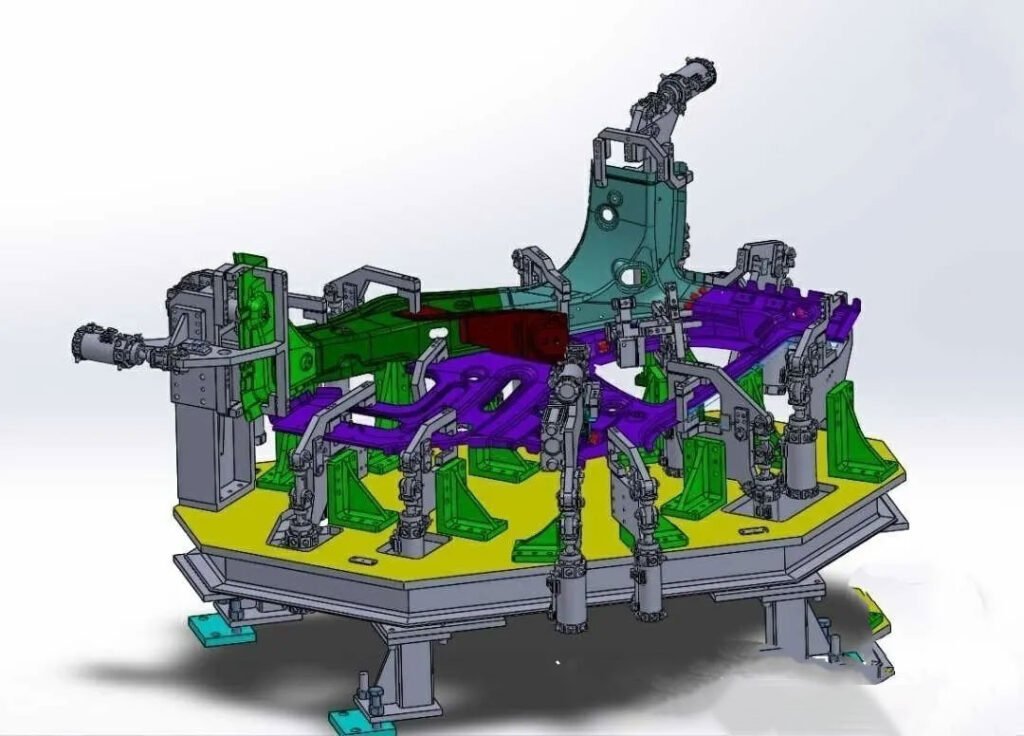
What we are talking about is one of the many types of fixtures, the automotive welding fixture. (Specialized fixture for automotive body-in-white welding)
An automobile body is composed of over 1,000 parts, most of which are made of sheet metal. After being stamped and formed using dies, these parts are often joined together by spot welding to form the body-in-white (BW). During welding, each part must be secured in place. This positioning and fastening tool is called a jig. Specialized jigs used in automobile body manufacturing are called body jigs (body equipment).
Through the coordinated action of the positioning pins (reference pins), S-surface blocks (reference surfaces), clamping arms and other components on the fixture, the workpiece (stamping part or assembly part) is installed in the position set by the process and clamped to prevent the workpiece from moving and ensuring the consistency and stability of the body welding accuracy.
Positioning: The workpiece is restricted in its six degrees of freedom in three-dimensional space by means of positioning pins (round pins/diamond pins), support blocks (iron or nylon) and other components.
Clamping: Use a cylinder or manual quick clamping mechanism to fix the workpiece to prevent welding deformation. The number of clamping points must match the welding requirements, and the workpiece deformation caused by the clamping force must be avoided.
Typical scenarios: Key parts such as vehicle body door openings and suspension holes require high-precision positioning to ensure the quality of subsequent assembly.
Reduce welding deformation caused by insufficient rigidity of thin plates (thickness 0.7-2.5mm) and ensure accurate welding point position (such as spot welding, arc welding, laser welding, etc.).
Some fixtures also have the function of inspection tools, which can detect the welding accuracy of the previous process.
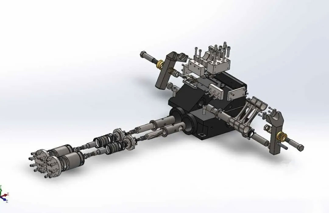
Automobile welding fixtures usually consist of the following modules:
| Components | Function | Design requirements |
| Fixture base plate (BASE board) | Basic platform that carries all positioning/clamping units | Flatness ≤0.1mm/1000mm, engrave coordinate grid lines, set reference holes (tolerance ±0.02mm) |
| Positioning unit (POST OR UNIT) | Including positioning pins, support blocks, limit blocks, etc. | Prioritize hole positioning and avoid surface positioning (difficult to process) |
| Clamping system | Cylinders, pressure arms and other power components | The clamping force needs to be calculated to prevent deformation of the workpiece; automated production lines often use pneumatic |
| Assistant System | Turning table, slide table, rotating mechanism, etc. | Provide operating space for welding clamps/robots to adapt to complex welds |
| Control System | Pneumatic/hydraulic system with safety interlock device | Prevent misoperation and ensure production safety |
Design Process
Process analysis: Decompose the digital model of the vehicle body to determine the distribution of weld points and process splitting (such as floor/front and rear panels/side panel assembly).
Structural design: Use CATIA, UG and other software for parametric modeling, and combine MCP (positioning point information) files to design the fixture structure.
Key design principles
Unified datum and error-proofing design : Molds, inspection tools, and fixtures use the same positioning datum to reduce tolerance accumulation, and add error-proofing pins (such as diamond pins and tapered pins) and anti-reverse structures to prevent workpiece misassembly.
Positioning logic
Limit all 6 degrees of freedom of the workpiece (3 translations + 3 rotations).
Typical Configuration
3 points on the main positioning surface (limit Z movement + X/Y rotation), 2 points on the side positioning surface (limit X movement + Z rotation), and 1 point on the end positioning surface (limit Y movement).
Exception handling
Large thin plate parts need to adopt the “N-2-1” principle (for example, 4-2-1) to prevent the workpiece from being deformed by gravity.
The clamping point layout should avoid the welding area (≥50mm), and air cylinder/hydraulic cylinder should be used to provide constant pressure.
The contact surface uses non-magnetic materials such as copper alloy and nylon to avoid magnetic field interference with the welding arc.
Use standardized substrates (such as EURO hole system)
Modular positioning units (such as MHD quick-change systems)
Gas/circuit integrated quick-connect interface
Car body mixed line production needs to support fixture switching within ≤5 minutes:
Ergonomic optimization
Operating height: Positioning surface 750-1100mm from the ground (suitable for standing/sitting work)
Maintenance space: ≥150mm wrench space is reserved for key bolts, and independent grooves are provided for sensor lines.
Predictive maintenance support
Vibration sensors are embedded in key motion pairs (such as guide rails and hinges)
Provide wear indicators (such as color-changing rings on pin sleeves)
Negative pressure fume extraction channel design (reduces welding spatter adhesion)
Reserve a minimum safety gap of 15mm (to prevent robot path jitter)
Intelligence: Combined with AI parametric design (such as developing automated programs on the CATIA platform) to shorten the design cycle.
Modularity: A library of standard parts (clamps, cylinders) speeds up fixture assembly and reduces manufacturing costs.
Welding fixtures are essentially a balancing act between precision, efficiency, and cost . With the application of new materials (carbon fiber reinforced composites) and AI visual compensation technology, future fixtures will transition toward “adaptive flexibility.” However, core design principles remain the foundation for ensuring accurate and stable welding with manufacturing certainty.